
Engineering a Diamond Wire Sawing Cut Indoors: Anchoring, Pulley Layout, Wire Path, and Sequencing for Thick Reinforced Nodes
Indoor “thick node” removal is rarely limited by cutting power. It’s limited by access, verification, rigging, and control.
When you’re inside a live facility—an airport mechanical room, a plant, a bank vault area, or a data environment—you’re engineering around realities like:
- 36-inch doorways and tight corridors
- no impact demolition (vibration is the enemy)
- embedded steel, plates, rails, and dense reinforcement
- strict work windows and clean handover expectations
- segment weight limits dictated by lifting method and haul-out route
This article lays out the real engineering logic behind a professional wire saw cut plan: what we verify, how we anchor, how we build the pulley layout and wire path, and how sequencing drives safety, cost, and schedule.
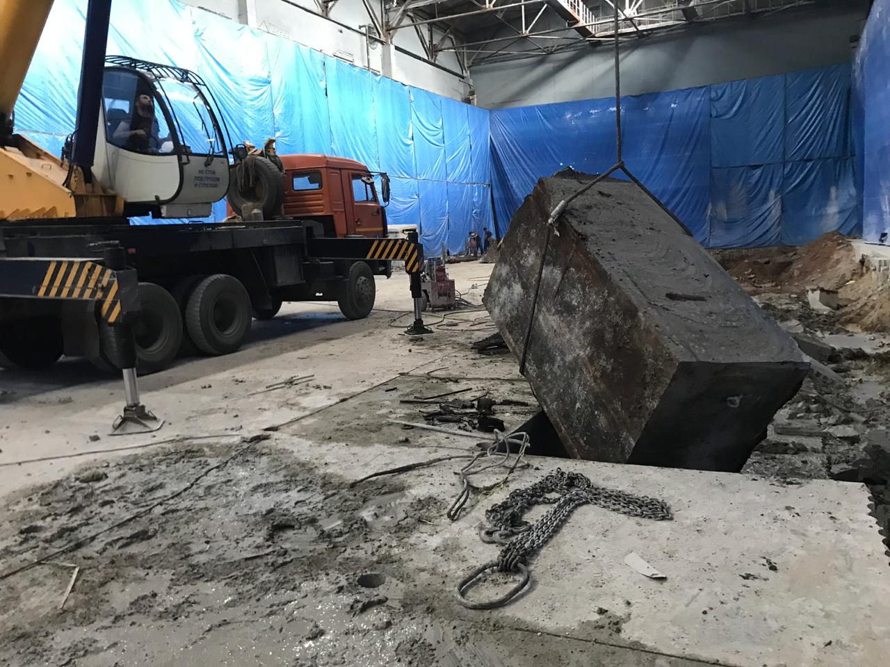
Why wire sawing becomes the default for thick indoor nodes
Diamond wire sawing wins indoors when any of the following are true:
- Thickness crosses the practical wall-saw range
In the field, indoor wall sawing is typically efficient up to ~12 inches (≈300 mm); beyond that, wire sawing often becomes the cleaner, more controllable solution. - The node contains “non-disc-friendly” steel
Heavy rebar (20 mm+), dense cages, embedded plates, rails, or structural steel elements can turn other methods into a slow, expensive grind. Wire sawing stays stable across mixed materials by design. - Mounting a track saw is hard or risky
Irregular geometry (beams, columns, odd-shaped pedestals), limited access, overhead constraints, or sensitive surroundings often make “just mount the saw” unrealistic. Wire sawing lets us cut at a distance. - Vibration is a hard constraint
Impact methods create vibration, noise spikes, and unpredictable cracking. Wire sawing is controlled, wet, and inherently low-vibration—often the only acceptable approach for live or sensitive spaces.
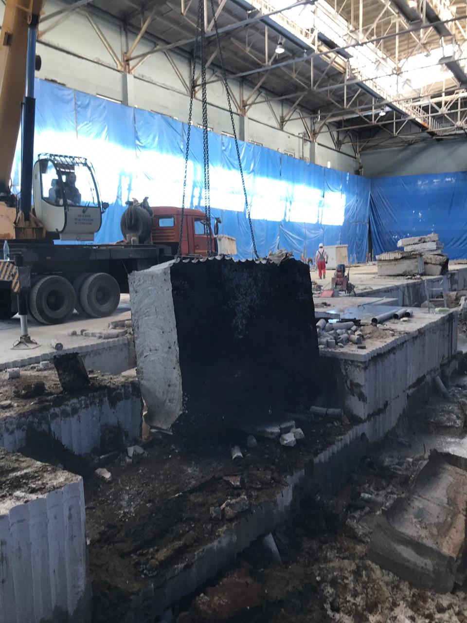
Industry guidance describes wire sawing as a method designed for thick concrete removal, using a diamond wire loop routed over pulleys and driven by a saw unit, typically with water for cooling and flushing.
Inputs we need before we design the cut plan
A “wire saw plan” is not just “where the cut goes.” It’s a combined plan for:
1) Geometry + thickness
- Element type: equipment foundation, wall opening, beam/column node
- Thickness (common thick-node decision range): > 12 inches (300 mm) becomes wire-favored; > 20 inches is almost always wire
- Total cut area (m² / ft²)
2) Verification (what’s inside)
- Rebar density and orientation
- Presence of post-tension (PT) cables, conduits, plumbing, embedded steel
- “Unknowns” that can change the method and the price
3) Access + bottlenecks
- Doorway widths (real-world limiting case: 36 inches with frame)
- Lift access and corridor constraints
- Staging space (where segments go before loading)
4) Rigging and haul-out strategy
- What can be used: pallet jack, dollies, chain fall, forklift, skid steer (sometimes)
- What often can’t be used indoors: excavator/mini-excavator with breaker (impact demo)
- Pick points and rigging control
- Segment weight targets (your typical indoor working corridor: ~300–750 kg)
Verification first: why scanning changes method, sequencing, and risk
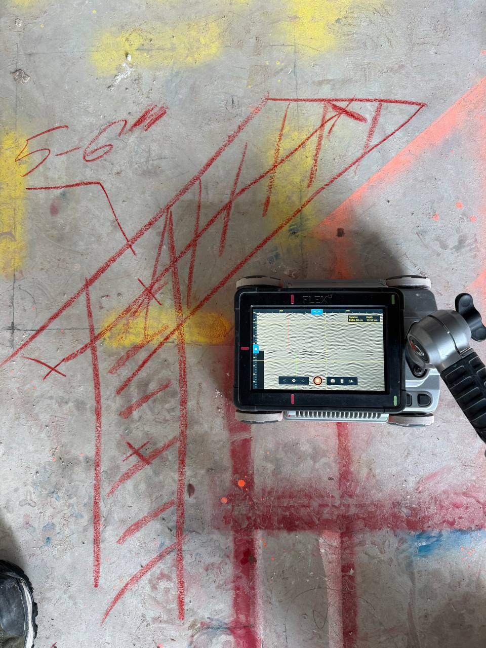
Before we drill threading holes or install anchors, we treat verification as a planning step—not an afterthought.
You’re already using professional tools (e.g., Geophysical Survey Systems, Inc. (GSSI) Flex LT and Hilti scanners). Manufacturer specs matter, but field reality matters more:
- Flex LT class systems commonly list up to ~30 in (75 cm) depth range in ideal conditions
- Practical depth and clarity reduce with dense rebar, fiber, and layered reinforcement, because the first dense layer can dominate reflections.
For embedded-object prevention, wall scanners commonly publish smaller localization depths (e.g., single-digit inches), which is why selecting the tool depends on the job and the question you’re answering.
Why this affects the cut plan:
- PT cables/conduits can force offset cuts, modified anchor locations, or a different method
- Knowing rebar layout helps reduce unnecessary “steel-crossing” time (less wear, faster cut)
- Scanning can prevent the most expensive outcome: a hit that becomes a shutdown
Anchoring the system: what we actually anchor—and why
A wire saw system anchors two different things:
- Cutting system guidance (posts/stands/rollers that define the wire path)
- Removal control (rigging points that prevent uncontrolled drop and allow safe handling)
Typical hardware logic (field reality)
- For guide posts/stands: mechanical expansion anchors in the M12 class (≈ 1/2") are common because they’re fast and repeatable
- Larger threaded sizes (e.g., M16 class ≈ 5/8") show up depending on load and hardware needs
Important engineering note: Anchors are not “all the same.” Their allowable loads depend on:
- embedment depth, edge distance, spacing
- concrete strength and cracking condition
- installation quality and hole cleanliness
So in cut planning, anchoring is engineered by:
- placing anchors away from edges and known reinforcement congestion where possible
- verifying drill points when risk is high
- keeping the rigging plan separate from the “roller stand plan”
Pulley layout and wire path: the real reason wire sawing is an engineering discipline
Wire sawing is “simple” in concept and highly sensitive in execution.
The wire loop is routed over pulleys and through pre-drilled holes, then driven by the saw unit.
1) Drive unit placement: you’re designing for stability and control
Indoors, you typically want:
- a stable base (often floor set-up)
- a wire path that stays out of walkways
- an operator position that is not in the line of the cut
2) Guide roller layout: you’re engineering “angle of attack”
Your own field rule is correct and important:
- If the wire enters too “flat,” it can polish (glaze), lose bite, and slow down
- If speed drops, you first adjust water, then adjust geometry by adding a roller to sharpen the entry angle
This logic matches manufacturer guidance that the wire entry geometry and pulley spacing affect performance and wire behavior.
3) Bend radius and pulley diameter: small radii destroy wire life
Even outside concrete cutting, wire rope guidance is consistent: tight bend radii increase fatigue and reduce service life.
In practical cut planning, this means:
- avoid tight pulley layouts when possible
- use enough distance to keep the wire running smoothly
- don’t force the wire through sharp, short turns “just to make it fit”
4) Corner management: remove sharp edges before the first run
Your field practice is exactly what professional wire plans require:
- knock down sharp corners before startup
- manually “pull through” to seat the wire
- then start the drive once the wire has a clean track
Why: sharp corners cause bead damage, strand shock, and premature wire failure.
A simple geometry rule that works in practice:
- acute direction changes (< ~90°) are high-risk
- a more open path (≈120° or more) is wire-friendly, especially on startup
Wire selection, loop length, and production: the numbers that control price
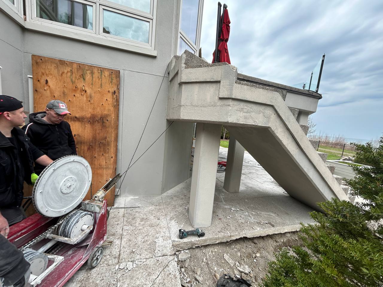
Typical wire spec (your field standard)
- 10.5 mm (≈ 0.41") galvanized diamond wire
- Loop length staged on the accumulator: 20–30 m (≈ 66–98 ft) depending on layout needs
Typical production (good conditions)
You shared a realistic baseline:
- ~8 m² per 8-hour shift (≈ 86 ft²/shift, ≈ 10.8 ft²/hour) for thick reinforced concrete when the setup is clean and the node is cooperative.
Hard-node production (dense steel / complex composite)
You also gave the right “hard truth” range:
- ~1 m² per 3–4 hours (≈ 2.7–3.6 ft²/hour) when the node is steel-heavy and slow.
Wire consumption (a metric that estimators should actually track)
Your rule of thumb is highly usable for planning:
- In ~16-inch (≈ 400 mm) thick reinforced concrete:
~2.0–2.5 m² per 1 m of wire
That’s ≈ 21.5–26.9 ft² per 3.28 ft of wire, or ≈ 6.6–8.2 ft² per foot of wire.
Where it gets better:
- thick mass concrete with lighter reinforcement can push higher yield
Where it collapses:
- composite nodes with lots of steel or long contact / poor geometry can drop dramatically (your note: down toward ~0.5 m² per meter in worst-case scenarios)
Sequencing and segment sizing: the cut plan is a haul-out plan
A wire saw “cut plan” is only correct if the segments can be:
- safely controlled at release
- moved through the building without damage
- staged and loaded without blocking operations
The simplest mass model (good enough for planning)
Use density × volume.
Normal concrete is often modeled around ~150 lb/ft³ (~2400 kg/m³).
You use ~2500 kg/m³ (~156 lb/ft³) as a practical reinforced-concrete planning number.
Example: your airport segment size (2 ft × 3 ft × 2 ft)
- Volume: 12 ft³
- Mass at 156 lb/ft³: ~1,872 lb (≈ 850 kg)
That’s a heavy indoor piece—still manageable with the right plan, but it explains why:
- doorway width
- lift method
- and staging space
become the limiting variables.
Practical indoor segment sizing rule
You already operate with two dominant grids:
- 3 ft × 3 ft when the route allows
- 2 ft × 3 ft when doors and corridors restrict
And this is where limited access becomes real: a 36-inch doorway is often the hard bottleneck.
Safety engineering: exclusion zones, line-of-fire, and operator position
Wire sawing safety is not “PPE only.” It’s geometry + separation.
Your standard is correct:
- No one in the line of cut
- Area taped off
- Operator positioned behind structure/offset from the wire path
- No uncontrolled access below (if overhead work exists)
Professional associations maintain dedicated safety standards and safe-work practice guidance for sawing and drilling operations. Concrete Sawing & Drilling Association
Case snapshots (real numbers, anonymized where needed)
Case #1 — Airport mechanical room: thick equipment foundations, zero-vibration priority
Scope: Remove 3 equipment foundations by wire sawing
Thickness: 24 inches (2 ft)
Segmentation: Each foundation cut into 4 blocks, each 2 ft × 3 ft × 2 ft
Total blocks: 12 blocks
Estimated mass (planning model):
- 1 block ≈ 850 kg (≈ 1,872 lb)
- 12 blocks ≈ 10.2 metric tons total concrete handled

Constraints:
- No impact demolition (vibration control)
- Tight access (36-inch door route, corridors, freight elevator)
- Verification mindset (scan first, then drill/thread/anchor)
Outcome: Controlled removal with minimal vibration and a clean handover.
Case #2 — International data facility: thick slab nodes with live-site discipline
Scope: Large-volume thick slab removal for upgrade work
Thickness: up to ~2.0 m (≈ 79 inches) in heavy zones
Crew: 7–10
Duration: ~20–25 shifts
Haul-out: ~30 trucks worth of concrete (site logistics-driven)
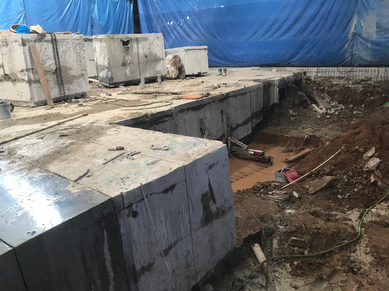
Constraints:
- Maintain operations in adjacent areas
- Low dust profile (wet cutting)
- Sequencing mattered more than raw cutting speed
Case #3 — Transit construction: thick wall removal with two-wire setup
Scope: Thick wall removal (excavation support / transit-related structure)
Thickness: ~1.5 m (≈ 59 inches)
Setup: 2 wire saw units, 2 operators
Duration: ~3 days
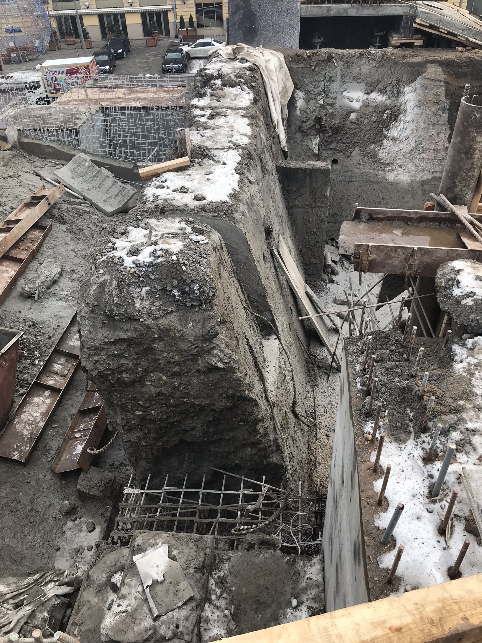
Why wire: Thickness and reinforcement profile + controlled removal requirements.
A practical “Wire Saw Cut Plan” template for engineers and estimators
If you want a cut plan that survives real indoor constraints, it needs these fields:
A) Verification
- What is embedded? (rebar layers, PT, conduit, pipe, steel plate)
- What tool + what depth expectation?
- Marking only or report required?
B) Access map
- Narrowest doorway width
- Elevator availability and capacity
- Turn points and staging zones
C) Rigging & handling
- Target segment weight range (indoor typical: 300–750 kg, unless heavier lifting is available)
- Release control method (pre-rig, chain fall, forklift, overhead crane)
- Where segments go immediately after cut (bin / trailer / staging)
D) Cutting geometry
- Entry/exit points
- Roller stand locations + anchor plan
- Pulley spacing plan to keep bend radius reasonable
- Corner prep plan (no sharp edges at startup)
E) Sequencing
- Cut order (to keep stability)
- Daily output expectation (good vs hard node)
- Cleanup and handover milestones
Next step: engineering site visit + test scan zone (commercial/industrial)
For commercial and industrial work, we can start with an engineering site visit + test scan zone—enough to confirm thickness and embedded conditions, and to design a cut/haul-out plan that won’t collapse on day one.
Frequently Asked Questions: Diamond Wire Sawing Cut Engineering (Indoor)
Search-intent answers on anchoring, pulley layout, wire path design, and sequencing for thick reinforced concrete nodes in limited-access indoor environments.